SledderWear.com - Snowmobile T-shirts & Gifts KawasakiTrax Forums & Message Board Community KawasakiTrax Home
TECH INFO: OIL INJECTION PUMP ADJUSTMENTS

Throttle Cable Adjustment

Do not operate the engine with the air box removed.
Removal will result in engine damage and may cause
carburetor icing and a stuck throttle.


1)Remove instrument panel mounting screws and air box assembly, then
hold the throttle lever at full throttle position and check that:

a. Both throttle valves inside the carburetor bore open fully and
equally. Be sure rear section of valve does not protrude into carburetor
bore to restrict air flow at full throttle. (see figure2-52)


b. With throttle lever at idle position, there should be approximately
1/16 inch (1.5mm) free play between the lever and housing.

The oil pump control arm must rest on the stop pin with the throttle at the idle
position. If either throttle valves, the throttle lever or oil pump control arm
requires adjustment, follow the procedure under "Carburetor and Oil Pump Synchronization".


Carburetor & Oil Pump Synchronization

Synchronization of the oil pump and carburetors is extremely important
to assure adequate engine lubrication and peak performance.

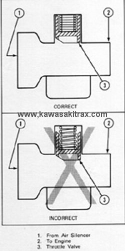
1) Loosen idle stop screws so that both throttle valves bottom out in the
carburetor bores.

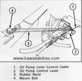
2) Push oil pump lever forward until it contacts the stop pin; this insures
that the oil pump is at the dead idle position. (see figure 2-53)


3) Adjust throttle cable on the LH carburetor so that all of the slack
is removed. The throttle valve should begin to raise as soon as the throttle
lever on the handlebar is moved.

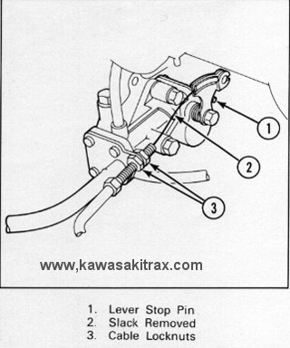
4) Loosen the locknuts on the oil pump cable, while holding the oil pump
lever against the stop pin, removing all of the cable slack. Adjustment is
correct when the lever on the oil pump and the throttle valve on the LH
carburetor move simultaneously as the throttle control lever is activated.

5) Adjust RH carburetor throttle cable so that oil pump lever and both throttle
valves move simultaneously as the throttle control lever is activated.

6) Perform any remaining carburetor adjustments as required.


Oil Injection System

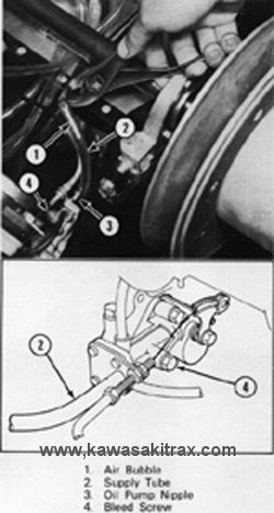
After performing maintenance on the oil injection system components or filling
the oil tank for the first time OR the oil tank has run empty, follow the procedures
under "Oil Injection System Bleeding" to insure adequate engine lubrication.

CAUTION: Failure to bleed trapped air from the oil injection system will result in severe engine damage.

Oil Injection System Bleeding

1) Remove instrument panel mounting screws and remove the air box assembly

2) Loosen the clamp and seperate the LH carburetor from its rubber mount.

3) Air trapped inside the oil pump assembly can be removed by squeezing (pulsing)
the oil pump supply hose with pliers. This process causes air to exit the oil pump
and travel up the supply hose. (see figure 2-64)


Continue squeezing (pulsing) the oil pump supply hose until air bubbles no
longer exit the oil pump assembly.

4) Remove bleed screw from side of oil pump and allow oil to drain until all
air bubbles are removed from the oil pump supply hose. Visually check the
entire length of the supply hose (from tank to pump) to be sure that no air
bubbles are present; then reinstall the bleed screw.

5) Reinstall LH carburetor and proceed to oil pump outlet tube purging procedure.


Oil Pump Outlet Tube Purging

Any air bubbles inthe oil pump outlet tubes may cause severe internal engine damage.
Perform OIL Injection Bleeding Procedure, then proceed as follows.

WARNING: Failure to disconnect the oil pump control cable when performing this
procedure will damage the cable. The damaged oil pump control cable can prevent the
throttle from returning to the idle position which mat lead to personal injury.

Use a remote fuel can with 40:1 premix while performing this procedure to insure
adequate oil is supplied to the engine until the oil pump can assume it's operation.


1) The oil pump inner cable must be disconnected from the control lever on the
oil pump to prevent damage to the cable. Do not disturb the outer cable locknuts
when removing the inner cable. (see figure 2-65)


2) Attach a rubber band to hold the oil pump control lever in the wide open position.
This will cause maximum flow of oil through the outlet tubes. (see figure 2-65)

3) Temporarily position the air box assembly onto the carburetors and secure
converter shield into proper position with clip pins to avoid injury.

4) Operate the engine at idle speed for 5 minutes, thenstop the engine.
This is ample time to purge all air from the oil outlet tubes

5) Remove air box assembly; remove rubber band and, reconnect the oil pump inner
control cable to the lever. Be sure to check operation of the oil pump control
lever by activating the throttle control lever on the handlebar.


Copyright 2012 KawasakiTrax Snowmobile Club